
DALY mainly has three protocols: CAN, UART/485, and Modbus.
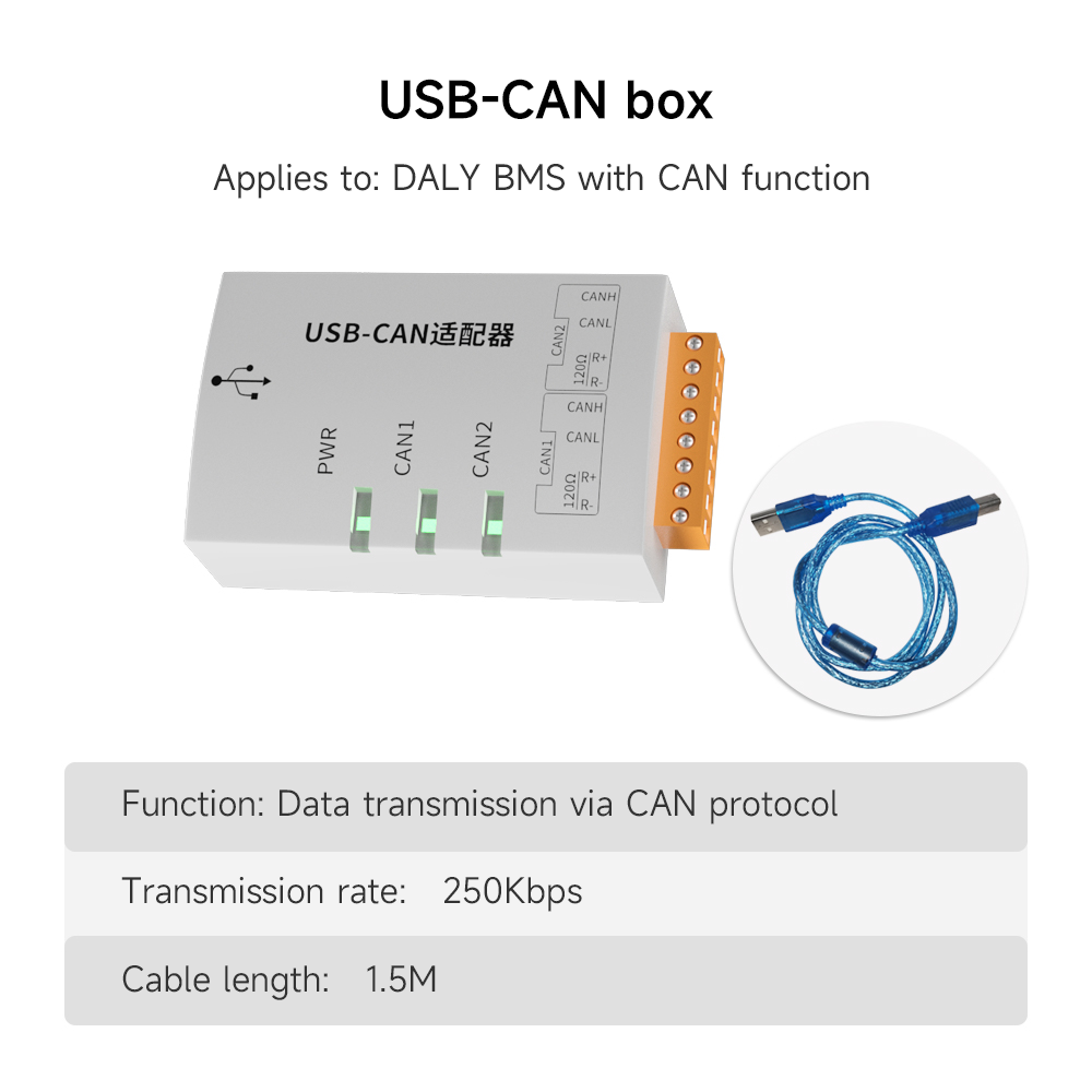
1. CAN Protocol
Test Tool: CANtest
- Baud Rate: 250K
- Frame Types: Standard and Extended Frames. Generally, the Extended Frame is used, while the Standard Frame is for a few customized BMS.
- Communication Format:Data IDs from 0x90 to 0x98 are accessible to customers. Other IDs are generally not accessible or modifiable by customers.Communication Content Information: For example, in the battery fault status with a secondary warning of low total voltage, Byte0 will display as 80. Converted to binary, this is 10000000, where 0 means normal and 1 means an alarm. According to DALY's high-left, low-right definition, this corresponds to Bit7: secondary warning of low total voltage.
- PC Software to BMS: Priority + Data ID + BMS Address + PC Software Address, e.g., 0x18100140.
- BMS Response to PC Software: Priority + Data ID + PC Software Address + BMS Address, e.g., 0x18104001.
- Note the position of the PC Software Address and the BMS Address. The address receiving the command comes first.
- Control IDs: Charging MOS: DA, Discharging MOS: D9. 00 means on, 01 means off.
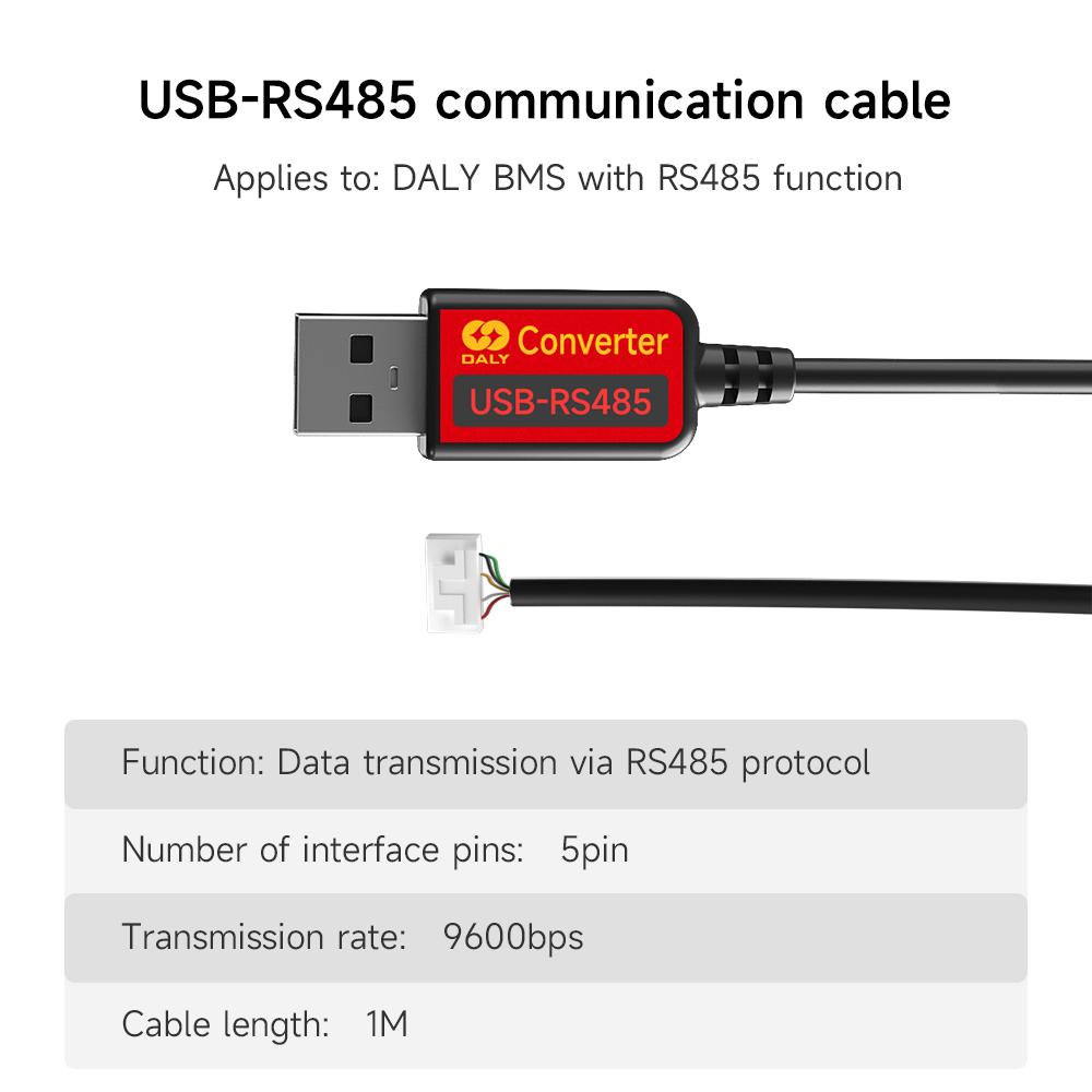
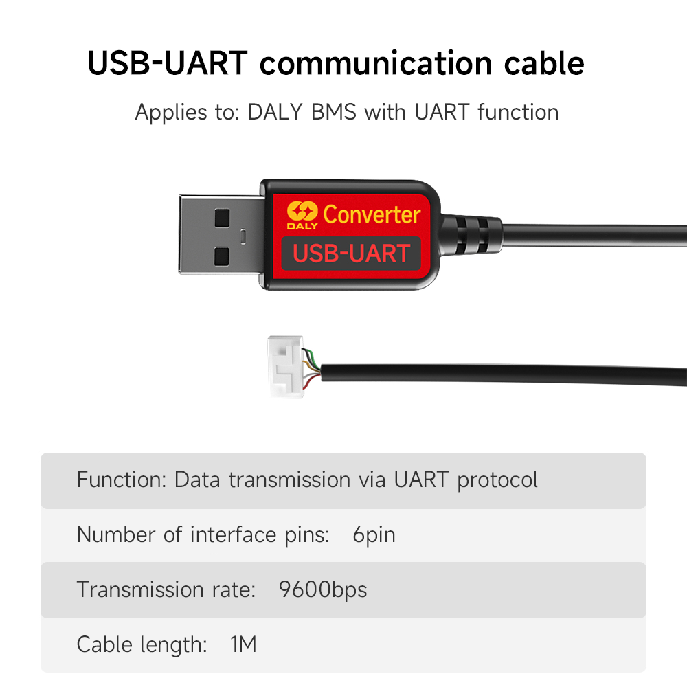
2. UART/485 Protocol
Test Tool: COM serial tool
- Baud Rate: 9600bps
- Communication Format: Checksum Calculation Method: The checksum is the sum of all previous data (only the low byte is taken).
- PC Software to BMS: Frame Header + Communication Module Address (UPPER-Add) + Data ID + Data Length + Data Content + Checksum.
- BMS Response to PC Software: Frame Header + Communication Module Address (BMS-Add) + Data ID + Data Length + Data Content + Checksum.
- Communication Content Information: Same as CAN.
3. Modbus Protocol
Test Tool: COM serial tool
- Communication Format:
- Message Protocol Format: Read Register, Request Frame
- Byte: 0 | 1 | 2 | 3 | 4 | 5 | 6 | 7
- Description: 0xD2 | 0x03 | Start Address | Number of Registers (N) | CRC-16 Checksum
- Example: D203000C000157AA. D2 is the slave address, 03 is the read command, 000C is the start address, 0001 means the number of registers to read is 1, and 57AA is the CRC checksum.
- Standard Response Frame:
- Byte: 0 | 1 | 2 | 3 | 4 | 5 | 6 | 7 | 8
- Description: 0xD2 | 0x03 | Data Length | Value of 1st Register | Value of Nth Register | CRC-16 Checksum
- L = 2 * N
- Example: N is the number of registers, D203020001FC56. D2 is the slave address, 03 is the read command, 02 is the length of the data read, 0001 means the value of the 1st register read, which is the discharge status from the host command, and FC56 is the CRC checksum.
- Message Protocol Format: Read Register, Request Frame
- Write Register: Byte1 is 0x06, where 06 is the command to write a single holding register, byte4-5 represent the host command.
- Standard Response Frame: The standard response frame for writing a single holding register follows the same format as the request frame.
- Write Multiple Data Registers: Byte1 is 0x10, where 10 is the command to write multiple data registers, byte2-3 is the start address of the registers, byte4-5 represent the length of the registers, and byte6-7 represent the data content.
- Standard Response Frame: Byte2-3 is the start address of the registers, byte4-5 represent the length of the registers.
Post time: Jul-23-2024


