I.Introduction
With the widespread application of iron-lithium batteries in home storage and base stations, requirements for high performance, high reliability, and high-cost performance have also been put forward for battery management systems.
This product is a universal interface board specially designed for household energy storage batteries, which can be widely used in energy storage projects.
II.functionalities
The parallel communication function queries BMS information
Set BMS parameters
Sleep and wake
Power consumption(0.3W~0.5W)
Support LED display
Parallel dual RS485 communication
Parallel dual CAN communication
Support two dry contacts
LED status indication function
III.Press to sleep and wake
Sleep
The interface board itself does not have a sleep function, if the BMS sleeps, the interface board will shut down.
Wake
A single press of the activation button wakes up.
IV.Communication Instructions
RS232 communication
The RS232 interface can be connected to the host computer, the default baud rate is 9600bps, and the display screen can only choose one of the two, and cannot be shared at the same time.
CAN communication, RS485 communication
The default communication rate of CAN is 500K, which can be connected to the host computer and can be upgraded.
RS485 default communication rate 9600, can be connected to the host computer and can be upgraded.
CAN and RS485 are dual parallel communication interfaces, that support 15 groups of battery parallel
communication, CAN when the host is connected to the inverter, RS485 should be parallel, RS485 when the host is connected to the inverter, CAN should be parallel, the two situations need to brush the corresponding program.
V.DIP switch configuration
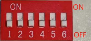
When the PACK is used in parallel, the address can be set through the DIP switch on the interface board to distinguish different PACKs, to avoid setting the address to the same, the definition of the BMS DIP switch refers to the following table. Note: Dials 1, 2, 3, and 4 are valid dials, and dials 5 and 6 are reserved for extended functions.

VI.Physical drawings and dimensional drawings
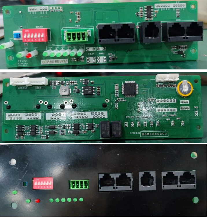
Reference physical picture: (subject to the actual product)

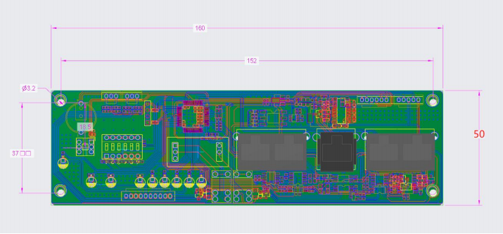
Motherboard size drawing: (subject to the structure drawing)

Post time: Aug-26-2023


